
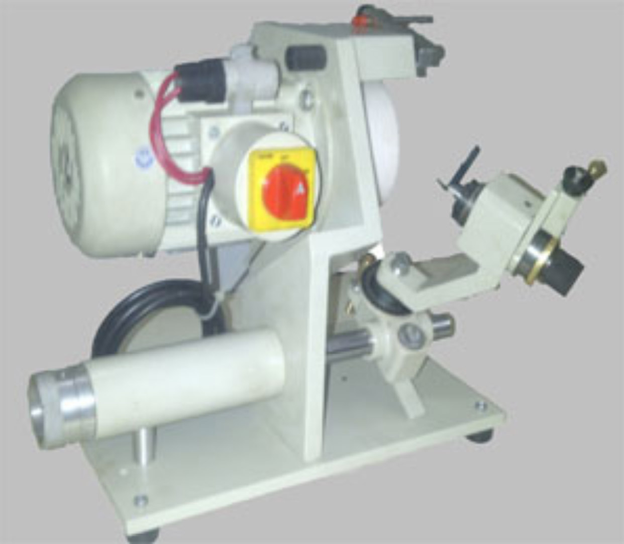
The Sg-Cg-100 Was Exclusively Developed For The Economical Grinding Of Cutters Used For Engraving, Die Sinking And Fine Boring Tools. Tools Work Best When They Are Ground to a High Degree of Accuracy. The Grinding Angle Can Be Adjusted To The Desired Angle.
Cutter Grinding Machines Always Ensure That Cutters Are Perfectly Ground And Sharp.
The Quality Of Finish That A Well Ground Cutter Generates Will Be Far Superior That One Ground By Hand. Furthermore Cutters Ground In A Machine Will Give Faithful And Precise Reproduction At Lower Cost. Grinding Generates A Lot Of Dust- This Machine Uses A Totally Enclosed Motor And Provides Unchallenged Performance.
Specifications
All Dimensions In Mm.
Motor-T Single Phase- Totally Enclosed Fan Cooled
240v 2800 Rpm 100 Watts
Grinding Wheel - 100 Mm Diameter.
Machine Dimensions - (Lx Bxh) 410 X 215 X 250
Box Dimensions- (Lxbxh) 440 X 245 X 280
Weight Net- 18 Kg Gross – 22 Kg
Work Capacity
Maximum Cutter Diameter – 8 Mm
Fine Feed Movement – 22mm – 0.05 Increment.
Standard Equipment (With The Machine)
Aluminium Oxide Cup Wheel One
Cutter Spindle Complete One
Collet 1/8” One
Collet 1/4” One
Allen Key One
Spanner One
Dusting Brush One
Instruction Manual One
Optional Equipment (Order Separately)
Diamond Grinding Wheel (For Carbide Tools)
OPERATION OF THE MACHINE
FAST ACCURATE GRINDING MADE EASY
1. Cutter to be ground.
2. Cutter Spindle. The cutter is gripped in a collet. It is by using different sizes of collets to grind cutters up to 10mm in diameter.
3. Locking Screw for the tool holder. This can be removed and replaced by another holder for different applications.
4. Locater Gauge for cutter positioning.
5. Clearance Angle Setting- This is the thimble, which makes it possible to obtain the clearance angle. The adjustment is made against a stop setting plate. Setting is simple. It is only necessary to rotate the thimble to the angle chosen and lock the adjusting screw.
6. Knurled Knob for turning the tool.
7. Sliding Beam for longitudinal movement.
8. Tool Holder assembly having two movements. Graduated Base to set the included angle for the cutter. Horizontal sliding to allow for in-feed of the cutter. Micrometre movement for the axial movement of the cutter graduated to 0.05 per division.
9. Locking Lever for the tool holder assembly to position when the point angle has been set.
10. Adjustment screw to limit the sliding beam in its angular position.
11. Diamond Dresser attachment for dressing the wheel with fine feed. This accessory is fitted on the wheel guard for dressing the wheel whenever necessary. Knurled screw for micrometric adjustment of the diamond.
12. Lock Screws for easy removal and replacement of the grinding wheel.
UNPACKING THE MACHINE
The machine is packed in a sturdy carton. The cutter head and standard accessories are packed separately and are in the carton. After removing the machine carefully examine all wrapping papers to ensure no items are left behind.
SETTING THE MACHINE FOR USE
Set the machine on a sturdy table near an electrical point duly grounded. 220 volts AC. It is essential a well-lighted location be selected for the work place. Slide the cutter head on to the machine guide bar and lock in the desired position.
CUTTER HEAD
The Cutter Head is the work holding fixture which is designed as an index head and is held on a bar guide. The bar guide has a fine micrometric adjustment movement in the longitudinal direction. Accurate position can be facilitated by a graduated collar to (0.05mm) The cutter head can be pivoted relative to the bar guide to set for the included angle of the cutter.
GRINDING WHEELS
Use Aluminium Oxide wheels for grinding HSS Cutters.
Use Silicon Carbide wheels for grinding Carbide Cutters.
Use Diamond wheels for final finishing of Carbide Cutters.
DRESSING THE GRINDING WHEEL
Aluminium and silicon grinding wheels may be dressed with a diamond dresser. The attachment for dressing is fitted in the wheel guard. Clamp the diamond dresser with the thumbscrew in the desired position. In feed by the knurled screw allows the dresser to approach the wheel. To and fro oscillation is manual for the wheel dressing. NOTE- DO NOT uses the diamond dresser to dress a diamond wheel.
STEPS IN GRINDING SINGLE LIP CUTTERS
Rough grind the cutter to slightly more than half on an off hand grinder. Select a suitable collet for the cutter. Insert the collet and gently tighten with the draw bolt. Then insert the tool to protrude about 20mm and clamp the cutter firmly. Do not over tighten.
Adjust the head on the guide bar, so that it is positioned in a way to grind the front face.
Using the in feed, finish grinds the cutter to exactly one half the cutter diameter.
Now, loosen the cutter, allow the cutter to align with the finger and reclamp firmly.
Set the degree required by using the protractor scale to get the included angle.
Withdraw the index pin- rotate the cutter using the draw bolts, simultaneously using the in feed. This operation will grind the cutter to a conical point.
The setscrew purpose to adjust the cutter for the desired clearance angle.
NOTE- While grinding cutters, use an average in feed, so that the cutter does not get burnt while being ground. Never grind the front face of the cutter so as to lose the centre line.
REGRINDING THE CUTTER
Insert the cutter in a suitable collet and tighten with the draw bolt. Cutter should extend about 20mm
Set the included angle as dictated by the cutter. Then proceed in a manner as previously described.